Describe how Object-Oriented Languages allow Programmers to define New Data Types as needed.
Describe how Object-Oriented Languages allow Programmers to define New Data Types
Traditional computer programming languages have a finite set of data types, typically several variations of integers, a couple of different kinds of floating-point numbers, a string and/or character type, and maybe a boolean type. These types are fine as long as that's the sort of data you are working with, but what do you do when you need a more complicated type, such as an employee type? Object-oriented languages allow programmers to define new data types as needed. These types are called classes. Initially, classes are built up out of the primitive types of the language. For example, a Point class might be composed of two primitive floating-point numbers that represent the coordinates of the point on a plane, possibly named x and y. This Point class can be represented in a reasonably language-independent fashion using a class diagram, as shown here:
A class diagram is divided into compartments. The name if the class is given in the bold face type in the top or name compartment.
The attributes of the class, that is the values, which define the state of the class, are given in the bottom compartment, the attribute compartment.
This diagram indicates that this Point class has two attributes, also known as fields or member variables, called x and y, and that each of these is a floating-point number.
Floating-point Numbers
Floating-point numbers are rational numbers, that is, numbers with decimal points, such as 76.5 or -1.0. In this course, we do not care how a particular language implements floating-point values. The same is true for the integer and string data types. All that is important is that these are data types that can contain an integer or a text string. In computing, floating point describes a method of representing an approximation of a real number in a way that can support a wide range of values. The numbers are, in general, represented approximately to a fixed number of significant digits (the significand) and scaled using an exponent. The base for the scaling is normally 2, 10 or 16. The typical number that can be represented exactly is of the form:
Floating-point Representation: The idea of floating-point representation over intrinsically integer fixed-point numbers, which consist purely of significand, is that expanding it with the exponent component achieves greater range. For instance, to represent large values, e.g. distances between galaxies, there is no need to keep all 39 decimal places down to femtometre-resolution (employed in particle physics). Assuming that the best resolution is in light years, only the 9 most significant decimal digits matter, whereas the remaining 30 digits carry pure noise, and thus can be safely dropped. This represents a savings of 100 bits of computer data storage. Instead of these 100 bits, much fewer are used to represent the scale (the exponent), e.g. 8 bits or 2 decimal digits. Given that one number can encode both astronomic and subatomic distances with the same nine digits of accuracy, but because a 9-digit number is 100 times less accurate than the 11 digits reserved for scale, this is considered a trade-off exchanging range for precision. The example of using scaling to extend the dynamic range reveals another contrast with fixed-point numbers: Floating-point values are not uniformly spaced. Small values, close to zero, can be represented with much higher resolution (e.g. one femtometre)
than large ones because a greater scale must be selected for encoding significantly larger values.
That is, floating-point numbers cannot represent point coordinates with atomic accuracy at galactic distances, only close to the origin.
The term floating point refers to the fact that a number's radix point (decimal point) can "float". That is, the decimal can be placed anywhere relative to the significant digits of the number. This position is indicated as the exponent component in the internal representation, and floating point can thus be thought of as a computer realization of scientific notation.
Over the years, a variety of floating-point representations have been used in computers. However, since the 1990s, the most commonly encountered representation is that defined by the IEEE 754 Standard[1]. The speed of floating-point operations, commonly referred to in performance measurements as FLOPS, is an important characteristic of a computer system, especially in software that performs large-scale mathematical calculations.
The three terms, 1) attribute, 2) field, and 3) variable, are interchangeable, though different versions are preferred in different languages. For this course, will stick to the most generic term, attribute.
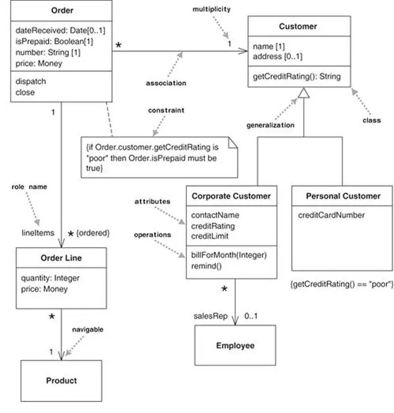
The class diagram is not only widely used but also subject to the greatest range of modeling concepts. Although the basic elements are needed by everyone, the advanced concepts are used less often. A class diagram describes the types of objects in the system and the various kinds of static relationships that exist among them. Class diagrams also show the properties and operations of a class and the constraints that apply to the way objects are connected. The UML uses the term feature as a general term that covers properties and operations of a class. Figure 5-3 shows a simple class model that would not surprise anyone who has worked with order processing. The boxes in the diagram are classes, which are divided into three compartments: the name of the class (in bold), its attributes, and its operations. Figure 5-3 also shows two kinds of relationships between classes: associations and generalizations.
Figure 5-3 : A simple Class Diagram
Reverse Engineering
The vice-versa direction-source code to diagrams--is commonly referred to as reverse engineering. Compiled Java code contains enough information that you can also reverse engineer from the compiled file back to diagrams as well. Actual source code is not necessary. Most other languages, such as C++, are not so easy to reverse engineer. Reverse engineering is the process of discovering the technological principles of a device, object, or system through analysis of its structure, function, and operation. It often involves disassembling something (computer program, chemical, or organic matter) and analyzing its components and workings in detail, just to re-create it. Reverse engineering is done for maintenance or to create a new device or program that does the same thing, without using the original. The other reason Reverse engineering is carried out is to duplicate the original software. Reverse engineering has its origins in the analysis of hardware for commercial or military advantage. The purpose is to deduce design decisions from end products with little or no additional knowledge about the procedures involved in the original production. The same techniques are subsequently being researched for application to legacy software systems to replace incorrect, incomplete, or unavailable documentation.
The Use of Diagrams in Practice The fact that the UML is a detailed specification does not mean that every aspect of it must be used at all times. In fact, a proper subset of this notation is sufficient to express the semantics of a large percentage of analysis and design issues. We will highlight this subset during our presentation of the notation in this chapter. Why, then, bother with the detail beyond this subset? Quite simply, such detail is necessary to express certain important tactical decisions. Additionally, some detail exists in the infrastructure of the UML, of interest to tool vendors, which facilitates the creation of forward-engineering and reverse-engineering tools. Such internal details enable the integration of front-end CASE tools that support this notation together with software development environments that focus on manipulating the products of the object-oriented programming language.
The diagram style we'll be using here is taken from the Unified Modeling Language, UML for short. This is one of the most common diagramming styles used. The above diagram can be implemented in any object-oriented language such as Java.
Java Implementation of Class Diagram
Point
x: Floating Point y: Floating Point
Floating Point: In Java, the program corresponding to this diagram would be written like this:
class Point {
  double x;
  double y;
}
In Java, all code is grouped into classes, where the Java Class is thus a code container. The definition of the class starts with an access modifier, which specifies which classes have access to it. This is followed by the keyword class and the name of the class (Point).
Every class definition is enclosed within brackets {}.
public class Point{

}
It has variables (x,y) and no methods as of yet. The main method (in Java) is a special method since it is the entry point of program execution.
In other words, when the class Point is run by the Java Runtime Environment, it will start by executing the main method.
Note that not every Java class should have a main method.
Class Diagrams
Class diagrams are used to describe the structure of the system. Classes are abstractions that specify the common structure and behavior of a set of objects. Objects are instances of classes that are created, modified, and destroyed during the execution of the system. An object has state
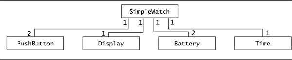
that includes the values of its attributes and its links with other objects. Class diagrams describe the system in terms of objects, classes, attributes, operations, and their associations. For example, Figure 5-3 is a class diagram describing the elements of all the watches of the SimpleWatch class. These watch objects all have an association to an object of the PushButton class, an object of the Display class, an object of the Time class, and an object of the Battery class. The numbers on the ends of associations denote the number of links each SimpleWatch object can have with an object of a given class. For example, a SimpleWatch has exactly two PushButtons, one Display, two Batteries, and one Time. Similarly, all PushButton, Display, Time, and Battery objects are associated with exactly one SimpleWatch object.
Figure 5-3: A UML class diagram describing the elements of a simple watch.
C++ Class Diagram Implementation
Point
x: Floating Point y: Floating Point
In C++, the program corresponding to this diagram would be written like this:
class Point {
  double x;
  double y;
};
Discovering Classes:
If you find yourself defining a number of related variables that all refer to the same concept, stop coding and think about that concept
for a while. Then define a class that abstracts the concept and contains these variables as data fields.
Suppose you read in information about computers. Each record contains the model name, the price, and a score between 0 and 100.
You are trying to find the best result using the least amount of effort.
The product for which the value (score/price) is highest.
The following program finds this information for you.
bestval.cpp
#include < iostream >
#include <string >

using namespace std;
int main()
{
 string best_name = "";
 double best_price = 1;
 int best_score = 0;
 bool more = true;
 while (more){
  string next_name;
  double next_price;
  int next_score;
  cout << "Please enter the model name: ";
  getline(cin, next_name);
  cout << "Please enter the price: ";
  cin >> next_price;
  cout << "Please enter the score: ";
  cin >> next_score;
  string remainder; // Read remainder of line
  getline(cin, remainder);
  if (next_score / next_price > best_score / best_price){
   best_name = next_name;
   best_score = next_score;
   best_price = next_price;
  }
  cout << "More data? (y/n) ";
  string answer;
  getline(cin, answer);
  if (answer != "y") more = false;
 }
 cout << "The best value is " << best_name
 << " Price: " << best_price
 << " Score: " << best_score << "\n";
 return 0;
}
In fact, a good CASE (Computer-Aided Software Engineering) tool can convert diagrams into source code in various languages and vice versa.
[1]IEEE 754 Standard: The IEEE 754 Standard, also known as the "floating-point standard," is a technical specification established in 1985 by the Institute of Electrical and Electronics Engineers (IEEE) that defines how computers represent and manipulate real numbers.