| Lesson 6 | Interfaces |
| Objective | Convert events to operations. |
Complete the event Description
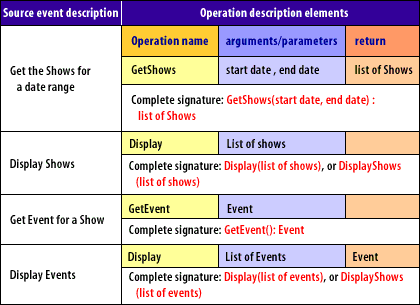
Complete the event description by adding information that is passed along with the event and the expected answer or response.
Both of these elements are optional, that is, not every event requires parameters and not every event requires a response.
For example, an event called "notify" from one context might be as simple as an alarm with no parameters and no return. In another context, "notify" might mean "send a message and wait for a reply."
For example, an event called "notify" from one context might be as simple as an alarm with no parameters and no return. In another context, "notify" might mean "send a message and wait for a reply."
- Convert event descriptions to Operations
The goal of creating the sequence diagram is to discover and document the interfaces of each class. To define each interface fully, you must convert the event description to a formal operation signature. The standard definition for an operation signature consists of a name, input parameters (or arguments), the expected return data type, and constraints.
How do Interfaces define an Operation?

- Operation name: required
- Any number of arguments is allowed
- Return data type: required for a return value, but return values themselves are optional
- Visibility: required before code generation
- Class operation: optional
- Argument name: required for each argument, but arguments themselves are optional
- Argument data type: required for each argument, but arguments themselves are optional
- Constraints: optional
In Unified Modeling Language (UML), interfaces play a crucial role in defining operations, especially in the context of object-oriented design. An **interface** is a collection of abstract operations (methods) that define a contract or a set of behaviors that a class must implement. Here's how interfaces define operations in UML:
By using interfaces to define operations, UML promotes modularity, reusability, and clear separation of concerns in system design.
- Interface Definition
- An interface is represented in UML as a class rectangle with the keyword
«interface»above the interface name. - It contains abstract operations (methods) that specify what a class must do, but not how it should do it.
- Interfaces do not include attributes or implementation details.
«interface» +Printable ---------------------- +print(): void - An interface is represented in UML as a class rectangle with the keyword
- Operations in Interfaces
- Operations in an interface are abstract, meaning they have no implementation.
- They are defined by their name, parameters, and return type.
- Operations in an interface are typically public (denoted by the
+symbol in UML).
Example:
«interface»
+Drawable
----------------------
+draw(): void
+resize(scale: double): void
- Realization Relationship
- A realization relationship is used to show that a class implements an interface.
- In UML, this is represented by a dashed arrow with a triangular arrowhead pointing from the class to the interface.
- The class that implements the interface must provide concrete implementations for all the operations defined in the interface.
+Circle
----------------------
+draw(): void
+resize(scale: double): void
```
```
+Circle → «interface» Drawable
- Interface Operations in Class Diagrams
- When a class implements an interface, the operations from the interface are included in the class's operation list.
- The class must provide the implementation for these operations.
+Circle
----------------------
+draw(): void
+resize(scale: double): void
- Interface Operations in Component Diagrams
- In component diagrams, interfaces define the provided and required operations of a component.
- A provided interface (represented by a "lollipop" symbol) specifies the operations that the component offers.
- A required interface (represented by a "socket" symbol) specifies the operations that the component needs from other components.
- Interface Operations in Sequence Diagrams
- In sequence diagrams, operations defined in interfaces are used to show interactions between objects.
- The messages sent between objects often correspond to the operations defined in their interfaces.
- Interface Operations in Use Case Diagrams
- While interfaces are not directly used in use case diagrams, the operations defined in interfaces can be linked to the behaviors described in use cases.
- Interfaces define what operations a class must implement, not how.
- Operations in interfaces are abstract and have no implementation.
- Classes that implement interfaces must provide concrete implementations for all operations.
- Realization relationships in UML show how classes fulfill the contracts defined by interfaces.
By using interfaces to define operations, UML promotes modularity, reusability, and clear separation of concerns in system design.
Keep in mind that:
- Arguments (or parameters) are data elements that the object needs in order to perform the operation.
- The return data type describes the kind of information that must be given as a result of completing the operation.,
- Constraints are simply free-form text describing rules and limitations on the performance of the operation.
