| Lesson 9 | Deployment view |
| Objective | This page defines the purpose and function of the deployment view. |
UML Deployment View
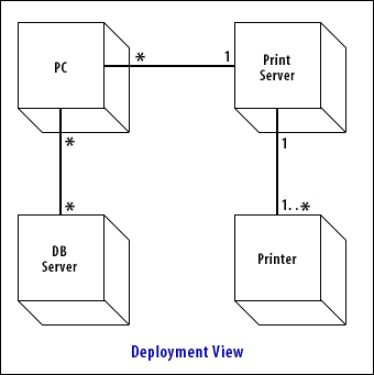
The deployment view addresses the need to map software to hardware. Typically, very different people and organizations manage these two environments, and
there is no easy way to model their relationships. Software is lost in a sea of production libraries, servers, and client installations, and hardware diagrams reveal nothing about the software running on the hardware components.

Map software to hardware
The deployment diagram allows the developer to represent the hardware environment in a notation very similar to that used for classes. Hardware is described in terms of features, functionality, and connectivity.
Software components, described using the component diagram, are then superimposed on the deployment diagram to map the relationships between the two directly.
Using this mapping technique, you can identify where software modules reside versus where they are loaded and run. Network communication requirements can be mapped by identifying first the software components that talk to one another and then their locations on the architecture. Likewise, architectural changes can be evaluated in terms of their effect on the software located on each node.
These models are not in general use yet; they tend to be used for discussion and planning. However, for people new to OO technologies, they can help reduce confusion through the use of simple diagrams and a shared notation for specifying new concepts. In the next lesson, the purpose and function of packages will be discussed.