| Lesson 6 | Use case view |
| Objective | The objective of this lesson is to define the purpose and function of use case view. |
Use Case View: Purpose, Function, and Modern Context
The use case view represents requirements from external actor perspective—what users want to accomplish without specifying how the system implements those goals. Originating from Ivar Jacobson's Object-Oriented Software Engineering (OOSE) methodology in 1992, use cases shifted requirements focus from implementation-centric functional decomposition toward user-centric goal achievement. This perspective—identifying actors (roles interacting with system) and use cases (goals actors want to achieve)—proved revolutionary because it deferred design decisions until understanding what the system must do for whom. Understanding the use case view's purpose and function requires examining both its enduring conceptual contributions and why contemporary practice largely replaced use case diagrams with alternatives like User Story Mapping, BDD scenarios, and Job Stories while retaining the actor-goal framework. The use case view continues providing value in specific contexts—regulatory documentation requiring formal requirements traceability, complex multi-stakeholder systems needing explicit actor identification, and legacy system understanding—while modern alternatives address collaboration, executability, and iterative refinement needs that static use case diagrams struggle to serve.
Purpose of the Use Case View
The use case view serves as requirements elicitation and validation mechanism addressing fundamental questions: Who uses the system? What do they want to accomplish? What value does the system deliver? Unlike traditional functional requirements specifying system behavior implementation ("The system shall validate credit cards using Luhn algorithm"), use cases specify user goals ("Customer completes purchase using credit card payment") deferring implementation to design phase. This separation—requirements (what/why) from design (how)—enables stakeholder validation before expensive implementation commitment. Business analysts can verify with customers that captured use cases match actual needs using vocabulary customers understand rather than technical jargon they don't.
The use case view facilitates communication across diverse stakeholders who struggle with technical specifications but readily understand actors and goals. Product managers discuss feature priorities by comparing use case importance and frequency. Marketing teams understand target users through actor definitions. Support organizations plan documentation around use case scenarios. Testers derive acceptance criteria from use case flows—each alternate flow becomes test case. This universal accessibility explains use case popularity in 1990s and 2000s—finally, a requirements technique business stakeholders could comprehend and validate without deep technical knowledge.
Function of the Use Case View
The use case view's primary function establishes system boundary—demarcating what the system does versus what external entities do. Actors exist outside the boundary; use cases inside. This distinction proves critical during scoping decisions. When stakeholders propose features, asking "is this a system use case or an actor responsibility?" clarifies whether functionality belongs in system scope or external integration. Consider e-commerce: "Customer browses products" might be use case, but "Customer receives package" is delivery company responsibility, not system's. The boundary establishes limits preventing scope creep while ensuring essential functionality receives attention.
Identifying actors reveals diverse stakeholders requiring system support, often surfacing requirements otherwise overlooked. **Primary actors** initiate use cases achieving their goals (Customer placing order). **Secondary actors** receive information or provide services the system needs (Payment Gateway processing transactions, Inventory System checking stock). **Offstage actors** have interest in use case outcomes without direct participation (Manager receiving sales reports). This actor categorization ensures system serves all stakeholders, not just most visible users. Regulatory compliance systems particularly benefit—identifying auditor actors ensures system maintains required audit trails for compliance verification.
Use case diagrams provide visual overview showing actors, use cases, and relationships among them. Stick figures represent actors. Ovals represent use cases. Lines connect actors to use cases they participate in. Relationships between use cases express behavioral structure: **«include»** indicates mandatory sub-behavior (ProcessPayment always includes ValidateCreditCard). **«extend»** indicates optional variation (PlaceOrder extends with ApplyCoupon only when customer provides coupon code). System boundary box encloses use cases, visually reinforcing scope. While diagrams provide overview, use case narratives—structured text documents—elaborate scenarios with preconditions, main flow, alternate flows, and postconditions providing implementation detail.
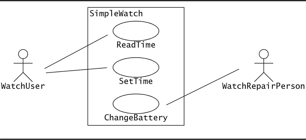
The simple watch example illustrates use case view fundamentals. **WatchUser** actor represents anyone wearing the watch, with goals of reading current time (ReadTime use case) and adjusting displayed time (SetTime use case). **WatchRepairPerson** actor represents specialized role with additional capability: changing watch battery (ChangeBattery use case). The model captures authorization constraint—only repair personnel access battery compartment—without specifying enforcement mechanism (physical lock? access code? design decides later). Three use cases inside system boundary represent complete watch functionality from user perspective. Any feature not representable as actor-initiated goal falls outside scope—watchband aesthetics matter but aren't system functionality.
Scenarios and Flow Details
Use cases elaborate through scenarios describing specific interaction sequences. The **main flow** (happy path) documents successful goal achievement under normal conditions. **Alternate flows** handle variations and business rule branches—different payment methods, expedited shipping, bulk discounts. **Exception flows** address error conditions—payment declined, item out of stock, network timeout. Each flow specifies preconditions (what must be true before flow begins), steps (actor and system actions), and postconditions (guaranteed outcomes). This structured narrative provides precision that diagram alone cannot convey, enabling developers to implement behavior and testers to validate correctness.
// Use Case Narrative Example: Place Order

Use Case: Place Order
Actor: Customer
Preconditions:
  - Customer authenticated
  - Shopping cart contains items

Main Flow:
  1. Customer selects "Checkout"
  2. System displays order summary with items, prices, total
  3. Customer confirms shipping address
  4. Customer selects payment method
  5. System validates payment information
  6. System processes payment
  7. System creates order record
  8. System sends confirmation email
  9. System displays order confirmation

Alternate Flow 3a: Customer updates address
  3a.1. Customer selects "Edit Address"
  3a.2. System displays address form
  3a.3. Customer enters new address
  3a.4. System validates address
  3a.5. Return to step 3

Exception Flow 6a: Payment declined
  6a.1. System receives decline notification
  6a.2. System displays payment error
  6a.3. System prompts for alternative payment
  6a.4. Return to step 4

Postconditions:
  - Order created in system
  - Inventory reserved
  - Payment processed
  - Confirmation sent to customer
Traceability and Guidance for Other Views
The use case view establishes requirements-to-implementation traceability essential for impact analysis and change management. Use cases trace to class diagrams (which domain classes support this use case?), sequence diagrams (how do objects collaborate implementing this scenario?), test cases (how do we verify this behavior?), and user documentation (what procedures accomplish this goal?). When requirements change—new regulation, business model shift, stakeholder request—traceability identifies affected design elements, test cases, and documentation requiring updates. This bidirectional traceability proves particularly valuable in regulated industries where demonstrating requirements coverage throughout development lifecycle satisfies compliance auditing.
Use cases guide design decisions in logical view by identifying necessary domain classes and their responsibilities. A "Place Order" use case implies Order, OrderItem, and Customer classes. Use case flows suggest class operations—"System validates payment" indicates need for payment validation logic. Use case relationships inform class relationships—if PlaceOrder includes ProcessPayment, the Order class likely depends on Payment processing functionality. This use case-to-class mapping (Robustness Analysis in some methodologies) bridges requirements and design, preventing design guesswork disconnected from actual user needs.
What Modern Practice Replaced
**User Story Mapping** (Jeff Patton, 2005) largely replaced use case diagrams for product planning and release scoping. Story maps arrange user activities horizontally creating journey backbone, with implementation stories stacked vertically beneath each activity. Teams collaboratively build story maps on walls or digital whiteboards (Miro, Mural), making planning participatory where use case diagrams felt academic. Story maps enable horizontal slicing (MVP cuts across activities), progressive elaboration (add detail incrementally), and visual prioritization (rearrange stories spatially). Unlike static use case diagrams created upfront then filed away, story maps evolve continuously as understanding deepens, remaining living artifacts throughout development.
// User Story Mapping: Modern Alternative to Use Case Diagrams

USER JOURNEY BACKBONE (horizontal activities):
┌────────────┬────────────┬────────────┬────────────┐
│   Browse   │   Select   │  Checkout  │   Track    │
│  Products  │   Items    │   Order    │  Delivery  │
└────────────┴────────────┴────────────┴────────────┘
      │            │            │            │
      v            v            v            v
IMPLEMENTATION STORIES (vertical priority):
┌────────────┬────────────┬────────────┬────────────┐
│ Search by  │ Add to     │ Enter      │ View       │
│ category   │ cart       │ shipping   │ status     │
├────────────┼────────────┼────────────┼────────────┤
│ Filter by  │ Update     │ Payment    │ Cancel     │
│ price      │ quantity   │ info       │ order      │
├────────────┼────────────┼────────────┼────────────┤
│ Compare    │ Save for   │ Apply      │ Track      │
│ products   │ later      │ coupon     │ shipment   │
└────────────┴────────────┴────────────┴────────────┘
         MVP RELEASE LINE ↑
(Slice horizontally for minimal viable product)

// Advantages over use case diagrams:
// - Collaborative workshop format (team creates together)
// - Visual journey representation
// - Easy MVP scoping via horizontal slicing
// - Lives on wall, constantly visible/updateable
**Behavior-Driven Development** (Dan North, 2006) transformed use case narratives into executable specifications through Gherkin syntax. Given/When/Then scenarios describe behavior in plain language while tools (Cucumber, SpecFlow, Behave) execute scenarios as automated tests. This executability addresses chronic use case problem: static documents diverging from implementation as code evolves. BDD scenarios fail when behavior changes without specification updates, ensuring living documentation that accurately reflects system behavior. The format remains accessible to business stakeholders (plain English) while providing developers executable acceptance criteria.
# BDD Scenario: Executable Alternative to Use Case Narrative

Feature: Order Placement
  As a customer
  I want to place orders for products
  So that I can purchase items conveniently

  Scenario: Successful order with credit card
    Given customer "Alice" is authenticated
    And cart contains:
      | Product  | Quantity | Price |
      | Widget   | 2        | $10   |
      | Gadget   | 1        | $25   |
    When customer confirms order
    And enters credit card "4111111111111111"
    And submits payment
    Then order "ORD-12345" is created
    And total is $45.00
    And confirmation email is sent to "alice@example.com"
    And inventory is decremented

  Scenario: Payment declined
    Given customer "Bob" is authenticated
    And cart contains 1 item
    When customer submits invalid card "4111111111111112"
    Then order is NOT created
    And error message "Payment declined" is displayed
    And cart contents are preserved

# Advantages over use case narratives:
# - Executable via Cucumber/SpecFlow (tests fail if out of sync)
# - Living documentation (always current)
# - Plain English readable by business stakeholders
# - Version controlled with code
**Job Stories** (Jobs-to-be-Done framework) reframe requirements by capturing situation-motivation-outcome rather than role-goal. Format: "When [situation], I want to [motivation], so I can [expected outcome]." This context-centric approach surfaces causality that use cases often omit. Use case: "Customer places order." Job Story: "When I find products I want while browsing on mobile during lunch break, I want to complete purchase in under 2 minutes, so I can buy without losing items before returning to work." The job story reveals constraints (mobile, time pressure) and motivation (fear of losing items) driving design decisions toward streamlined checkout—insights lost in abstract use case formulation.
Where Use Case View Remains Valuable
Regulated industries—medical devices (FDA), aerospace (DO-178C), automotive (ISO 26262), financial services (SOX)—require formal requirements documentation with traceability from stakeholder needs through design to test cases. Use case diagrams and narratives provide standardized format auditors recognize, tool support for traceability matrices, and formal structure satisfying regulatory documentation requirements. While BDD scenarios offer executability advantages, regulators often demand upfront requirements documentation before implementation—making traditional use cases better suited to compliance-driven processes than iterative agile approaches.
Systems with numerous distinct actor types benefit from explicit use case view. Healthcare systems serve patients, physicians, nurses, pharmacists, insurers, administrators—each with unique goals and authorization levels. Financial platforms support retail traders, institutional investors, market makers, regulators, compliance officers. Telecommunications systems interact with subscribers, network operators, billing systems, emergency services. Use case diagrams make these diverse actors visible, ensuring system design addresses all stakeholder needs rather than favoring most visible users. The actor taxonomy (primary, secondary, offstage) particularly helps during architecture decisions about authorization, audit logging, and notification routing.
Reverse-engineering legacy systems benefits from use case view providing functional overview before diving into code. Analyzing system behavior from external perspective—what can users do? what workflows exist? what actors interact?—builds understanding of system purpose independent of implementation details. This outside-in understanding proves more valuable initially than bottom-up code analysis, establishing context for subsequent detailed investigation. Use cases derived from legacy system observation guide modernization decisions—which use cases migrate to new platform? which consolidate as redundant? which retire as obsolete?
Modern Tooling for Use Case Documentation
When use case diagrams remain appropriate, modern tools provide lightweight alternatives to heavyweight CASE tools. **PlantUML** supports use case diagrams through text syntax, enabling version control and automated generation. **Mermaid.js** renders use case diagrams in Markdown for wikis and documentation sites. **draw.io** and **Lucidchart** provide collaborative visual editing without proprietary tool lock-in. These tools democratize use case modeling—teams can create diagrams without expensive software licenses or specialized training, lowering barriers to appropriate use case application.
// PlantUML: Text-Based Use Case Diagrams
@startuml
left to right direction
actor WatchUser
actor WatchRepairPerson

rectangle Watch {
  WatchUser -- (ReadTime)
  WatchUser -- (SetTime)
  WatchRepairPerson -- (ChangeBattery)
}
@enduml

// Mermaid: Markdown-Native Use Cases
```mermaid
graph LR
    WatchUser((WatchUser))
    WatchRepairPerson((WatchRepairPerson))

    WatchUser --> ReadTime[ReadTime]
    WatchUser --> SetTime[SetTime]
    WatchRepairPerson --> ChangeBattery[ChangeBattery]
```

// Advantages:
// - Version control (Git tracks changes)
// - No proprietary tools required
// - Generate in CI/CD pipeline
Integration with Modern Workflows
Modern practice applies use case view selectively rather than comprehensively. **Complex domains** benefit from formal use case analysis identifying all actors and goals before design. **Simple CRUD applications** skip use case view—User Story Mapping suffices. **Regulated systems** require use case documentation regardless of simplicity for compliance. **Agile teams** often start with User Story Mapping for collaborative planning, then formalize critical use cases requiring precise specification or regulatory documentation. This selective approach balances formalism's value with agility's speed, avoiding both over-documentation and under-specification.
Combining use case view with BDD creates powerful hybrid: use case diagrams provide static overview of system capabilities and actors, while BDD scenarios provide executable validation of specific use case flows. Use case serves as requirements documentation satisfying compliance needs; BDD scenarios serve as automated regression tests ensuring requirements stay implemented. This complementary approach addresses both documentation formality requirements and executable testing needs modern development demands.
Conclusion
The use case view's purpose—capturing functional requirements from external actor perspective before design commitment—remains conceptually sound. Its functions—establishing system boundary, identifying diverse actors, modeling user goals, providing requirements traceability—address genuine software engineering needs. However, contemporary practice evolved how these purposes get served: User Story Mapping provides collaborative planning that static use case diagrams lack. BDD scenarios offer executable specifications preventing documentation drift. Job Stories capture situational context informing design decisions. Modern tools (PlantUML, Mermaid) democratize use case creation when formal diagrams serve specific needs. Understanding use case view's enduring conceptual contributions enables informed decisions about when formal use case modeling serves needs—regulatory compliance, complex multi-stakeholder systems, legacy understanding, upfront architectural analysis—versus when modern alternatives provide superior value—collaborative discovery, iterative refinement, executable validation, continuous delivery workflows. The actor-goal framework persists across all approaches, demonstrating that use case view's core insight—understand what users want to accomplish before designing solutions—remains fundamental even as specific techniques evolve. Successful modern practice combines use case view concepts (actors, goals, boundary) with contemporary techniques (story mapping, BDD, job stories) appropriate to project context, regulatory requirements, and team capabilities rather than rigidly following any single methodology.
In the next lesson, the logical view, the most inclusive of the four views, will be discussed.