Identify the four fundamental modeling elements of a use case diagram.
Use Case Diagram
In UML (Unified Modeling Language), a use case diagram is a type of diagram that represents the functionality provided by a system in terms of actors, their goals (represented as use cases), and any dependencies between those use cases. The four fundamental modeling elements of a use case diagram are:
Actors: An actor represents a role played by a user or any other system that interacts with the subject (the system being modeled). Actors are external entities that initiate a use case by requesting the system to perform a function or task. They can be human users, external hardware, or other systems.
Use Cases: A use case is a specific functionality or a set of actions that the system performs to provide a measurable value to an actor. It represents a complete flow of events through the system in the context of a goal achievable by the interaction of an actor with the system. Use cases are depicted as ovals and are connected to their respective actors with lines, which can optionally be annotated to describe the nature of the interaction.
System Boundary (System Box): This is a rectangle that frames all the use cases of the system, defining the scope of the system. It visually separates the internal elements (use cases) of the system from the external elements (actors). The system boundary is optional but helpful in understanding the context and limits of the system being modeled.
Relationships: There are several types of relationships in a use case diagram, including:
Association: A line between an actor and a use case, indicating that the actor participates in the use case.
Include: A directed relationship between two use cases, indicating that one use case (the base use case) includes the functionality of another use case (the inclusion use case).
Extend: A directed relationship between two use cases, where one use case (the extension use case) adds new behaviors or actions to another use case (the base use case) under certain conditions.
Generalization: A relationship between actors or use cases, indicating that one actor/use case inherits the properties and behaviors of another actor/use case. It's used to show actor inheritance or use case inheritance.
These elements work together to describe the interactions and functionalities of a system from an outsider's perspective, focusing on what the system does and how it interacts with its users or other systems, rather than how the system is implemented.
The use case model has three components. The first component, and the only one actually defined by the UML, is the use case diagram.
To supplement the diagram, it is almost always necessary to add a use case narrative. Once a use case is fully described, it is possible to dissect it into scenarios, or test cases. Remember that although diagrams are extremely valuable and provide substantial information, they nearly always require some form of explanation to put them into context and ensure their proper interpretation.
The Use Case Diagram
Use case diagram
There are four modeling elements which make up the use case diagram:
Actor: People, systems, and devices that have a stake in the successful operation of the system.
System: Sets the context of the system in relation to the actors who use it and the features it must provide.
Use case: Identifies the key features of the system. Without these features, the system will not fulfill the user/actor requirements. Each use case expresses a goal that the system must achieve.
Association: Identifies an interaction between elements.
Elements of a Use Case Diagram
A use case diagram captures the business processes carried out in the system. Normally, domain experts and business analysts should be involved in writing use cases. Use cases are created when the requirements of a system need to be captured and a use case diagram is quite simple in nature and depicts two types of elements:
one representing the business roles and
the other representing the business processes.
Each association becomes a dialog that must be explained in a use case narrative[1]. Each narrative in turn provides a set of scenarios that function as test cases when evaluating the design and implementation of the use case.
In the next lesson, you will learn about the use case system element.
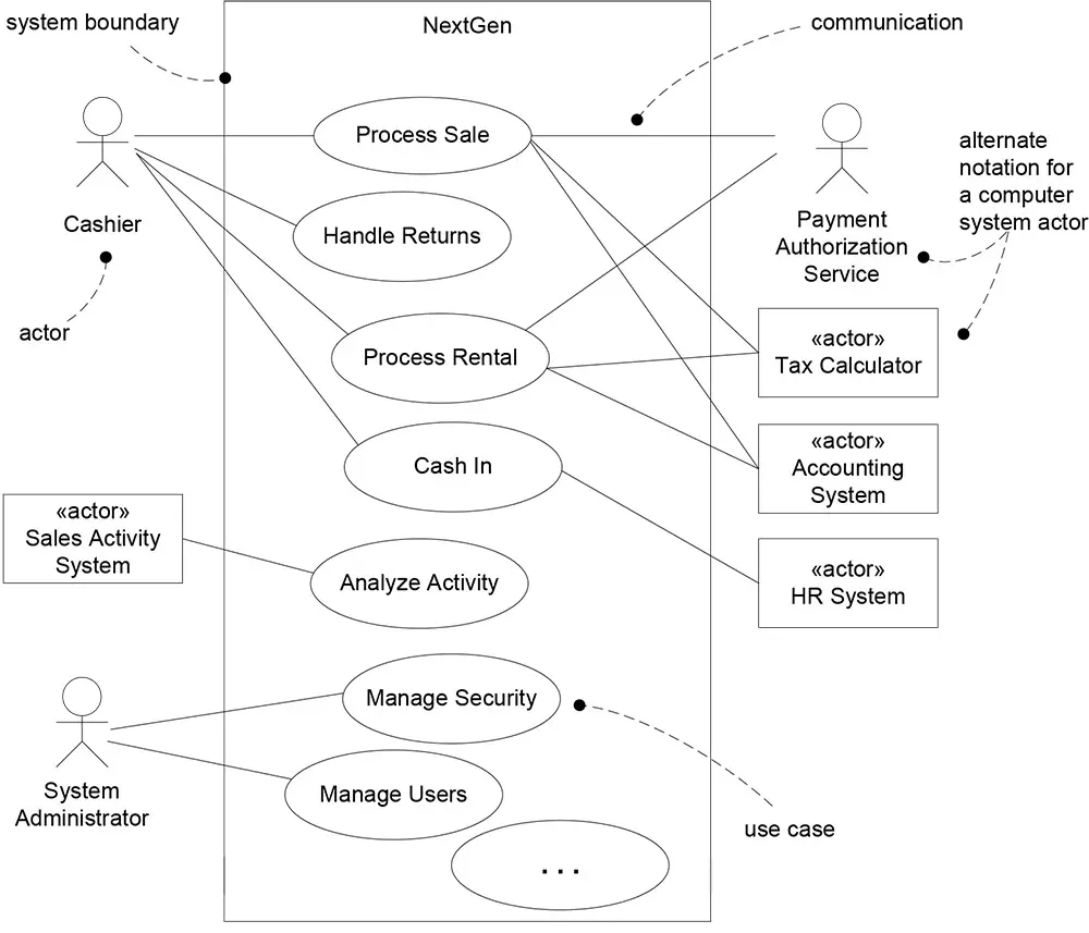
Use Case Diagrams
The UML provides use case diagram notation to illustrate the names of use cases can
actors, and the relationships between them (see Figure 3.3)
Figure 3.3 Partial use case context diagram
Use case diagrams and use case relationships are secondary in use case work. Use cases are text documents. Doing use case work means to write text. A common sign of a novice (or academic) use-case modeler is a preoccupation with use case diagrams and use case relationships, rather than writing text. World-class use case experts such as Anderson, Fowler, Cockburn, among others, downplay use case diagrams and use case relationships, and instead focus on writing. With that as a caveat, a simple use case diagram provides a succinct visual context diagram for the system, illustrating the external actors and how they use the system. Suggestion: Draw a simple use case diagram in conjunction with an actor-goal list. A use case diagram is an excellent picture of the system context; it makes a good context diagram, that is, showing the boundary of a system, what lies outside of it, and how it gets used. It serves as a communication tool that summarizes the behavior of a system and its actors.
Elements of Use Case Diagram
The diagram below shows the elements of a use case diagram.
Use case diagram
Use case: This element is used to identify a goal of the system.
Actor: This element could represent a role played by a person, a system, or a device that will use the system.
Association: This element describes the fact that two elements interact with each other.
System: This element represents the system in the context of the actors who use it and the features it must provide for them.
[1]use case narrative :A use case narrative is a text description of a system's functionality from the user's perspective.