| Lesson 5 | Four views into the software development process |
| Objective | Define the four classifications of the models included in the UML. |
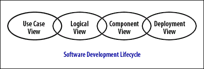
Four Views into Software Development: Organizing Architectural Perspectives
Complex software systems defy comprehension through single perspective—attempting to understand architecture, requirements, implementation, and deployment simultaneously overwhelms human cognitive capacity. Philippe Kruchten's 4+1 architectural view model, adopted by UML as organizing framework, addresses this complexity through separation of concerns: each view represents distinct stakeholder perspective using diagrams optimized for that viewpoint. The use case view captures functional requirements from user perspective. The logical view models domain concepts and design decisions. The component view specifies implementation structure and module organization. The deployment view documents physical architecture and hardware mapping. Understanding these views—their purposes, constituent diagrams, stakeholder audiences, and relationships—provides framework for selective UML application rather than attempting comprehensive modeling. Critically, modern alternatives evolved addressing specific view limitations: User Story Mapping replaces use case view for product planning, Event Storming enhances logical view for domain discovery, C4 Model simplifies multi-view architecture documentation, and Infrastructure as Code supersedes deployment view for automated provisioning. Examining the four views alongside contemporary alternatives enables informed decisions about when traditional UML views serve needs versus when modern approaches provide superior value.
The Need for Multiple Views
Software architecture exhibits essential complexity—distinct stakeholders care about different aspects requiring different representations. End users care about functionality, not implementation details. Developers need class structures and interaction protocols. System administrators focus on deployment topology and infrastructure. Project managers track component dependencies and integration risks. Attempting single diagram type serving all stakeholders produces either oversimplified diagrams lacking necessary detail or overwhelmingly complex diagrams useful to nobody. The solution: multiple views, each optimized for specific stakeholder concerns and architectural aspects.
Philippe Kruchten formalized this multi-view approach in 1995 through the **4+1 architectural view model**. Four fundamental views address distinct concerns: logical (domain model), process (runtime behavior), development (module organization), physical (hardware deployment). The "+1" represents use cases, which don't constitute separate view but rather scenarios cutting across other views demonstrating how they work together. UML adopted this framework, though terminology evolved—Kruchten's "development view" became "component view," "physical view" became "deployment view," and "process view" merged into "logical view" through interaction diagrams. The core insight persisted: architecture documentation requires multiple perspectives, each using appropriate notation for its concerns.
Use Case View: Capturing Functional Requirements
The **use case view** represents system functionality from external actor perspective—what users want to accomplish without specifying how system implements those goals. Use case diagrams show actors (roles interacting with system: human users, external systems, hardware devices) and use cases (goals actors want to achieve: "Place Order," "Generate Report," "Monitor Sensor"). Associations connect actors to use cases they initiate. Relationships between use cases («include» for mandatory sub-behavior, «extend» for optional variations) capture requirement structure. Use case narratives—structured text documents with preconditions, main flow, alternate flows, postconditions—elaborate scenarios with enough detail for implementation and testing.
The use case view serves multiple stakeholder needs. **Business analysts** elicit requirements by identifying actors and goals collaboratively with stakeholders. **Product managers** scope releases by selecting use case subsets for implementation phases. **Testers** derive acceptance test cases from use case scenarios—each alternate flow becomes test scenario. **Developers** understand system boundaries and functional scope before design begins. **Customers** validate that specified functionality matches their needs using vocabulary they understand—actors and goals rather than technical specifications.
Contemporary practice largely replaced use case diagrams for product planning while retaining the actor-goal conceptual framework. **User Story Mapping** (Jeff Patton) provides spatial visualization of user journeys—activities arranged horizontally (backbone), implementation stories vertically (walking skeleton through full-featured). Teams collaboratively build story maps on walls or digital whiteboards, making planning tangible and participatory where use case diagrams felt academic and detached. **Job Stories** (Jobs-to-be-Done framework) reframe requirements as situations triggering motivation: "When [situation], I want to [motivation], so I can [expected outcome]"—capturing context use cases often omit. **BDD scenarios** in Gherkin syntax (Given/When/Then) provide executable use case narratives validated through automated testing, addressing the documentation drift problem plaguing static use case documents.
// Use Case View: Traditional UML
Actor: Customer
Use Case: Place Order
  Preconditions: Customer authenticated, items in cart
  Main Flow:
    1. Customer selects "Checkout"
    2. System displays order summary
    3. Customer confirms order
    4. System processes payment
    5. System creates order record
  Alternate Flow 3a: Customer modifies items
    3a.1. Customer updates cart
    3a.2. Return to step 2

// Modern Alternative: BDD Scenario (Executable)
Feature: Order Placement
  Scenario: Successful order with valid payment
    Given customer "Alice" is authenticated
    And cart contains 3 items
    When customer confirms order
    And payment processes successfully
    Then order "12345" is created
    And confirmation email is sent
    And inventory is decremented

// Gherkin advantage: Executable via Cucumber/SpecFlow
// Tests fail if behavior diverges from specification
Logical View: Domain Model and Design
The **logical view** captures conceptual design—domain entities, their attributes and operations, and relationships among them—independent of implementation technology. Class diagrams form the logical view's core, showing classes (types defining structure and behavior), associations (semantic relationships enabling communication), aggregation and composition (whole-part relationships), generalization (inheritance hierarchies), and dependencies (usage relationships). Object diagrams complement class diagrams by showing specific instance configurations—snapshots illustrating patterns or complex structures concretely. Sequence and communication diagrams (formerly collaboration diagrams) model interactions among objects, capturing message flows implementing use case scenarios. State machine diagrams represent entity lifecycle, modeling how objects transition between states responding to events.
During software lifecycle, the logical view evolves through refinement. **Analysis** produces domain model identifying business concepts relevant to system—banking: Account, Transaction, Customer; healthcare: Patient, Diagnosis, Treatment. **Design** refines the model adding solution concepts—design patterns (Singleton, Factory, Observer), technical infrastructure (logging, caching, persistence), architectural layers (boundary, control, entity). **Implementation** further refines into code-level specifics with complete type signatures, exception handling, and detailed algorithms. This progressive refinement enables starting simple (analysis model) and elaborating incrementally rather than attempting comprehensive design upfront.
**Domain-Driven Design** significantly enhanced the logical view's expressiveness through tactical patterns providing richer domain modeling vocabulary than basic UML classes. **Entities** possess identity persisting over time—an Account with accountId maintaining identity despite attribute changes. **Value Objects** lack identity, defined entirely by attributes—a Money(100, USD) identical to any other Money(100, USD). **Aggregates** establish consistency boundaries grouping related entities under single root—Order aggregate containing OrderItems with Order as root controlling access. **Domain Events** capture significant occurrences—OrderPlaced, PaymentProcessed—enabling event-driven architecture. **Repositories** abstract persistence—OrderRepository provides collection interface hiding database details. UML class diagrams express these patterns using stereotypes («Entity», «ValueObject», «Aggregate») demonstrating how UML extensibility enables domain-specific customization.
**Event Storming** provides collaborative alternative to solitary class diagram modeling for domain discovery. Teams gather at long wall with unlimited colored sticky notes: orange for domain events (OrderPlaced, PaymentFailed), blue for commands (PlaceOrder, ProcessPayment), yellow for aggregates (Order, Payment), pink for external systems, purple for policies (business rules). Facilitators guide temporal ordering on timeline, surfacing hidden complexity, conflicts, and missing concepts through group discussion. Event Storming excels at strategic domain modeling—identifying bounded contexts, discovering aggregate boundaries, exposing organizational silos—complementing rather than replacing tactical UML class diagrams documenting discovered structure.
// Logical View: DDD Tactical Patterns in UML

«Entity»
class Order {
  - orderId: OrderId         // Identity (immutable)
  - customer: CustomerId
  - items: List<OrderItem>
  - status: OrderStatus
  + placeOrder(): void
  + addItem(item: OrderItem): void
}

«ValueObject»
class OrderId {
  - value: UUID
  // Immutable, equality by value
}

«ValueObject»
class Money {
  - amount: BigDecimal
  - currency: Currency
  + add(other: Money): Money
}

«Aggregate»
Order "1" *-- "*" OrderItem  // Composition: items part of Order

«DomainEvent»
class OrderPlaced {
  - orderId: OrderId
  - timestamp: Instant
  - customerId: CustomerId
}

// DDD patterns provide richer vocabulary than plain classes
// Stereotypes communicate tactical pattern choices
Component View: Implementation Structure
The **component view** specifies software module organization—source files, libraries, executables, packages—and dependencies among them. Component diagrams use rectangles with tabs representing deployable units: JAR files, DLLs, web services, microservices, NPM packages. Dashed arrows show dependencies (uses, requires, provides). This view addresses concerns distinct from logical view: while logical view models domain concepts, component view organizes implementation artifacts enabling parallel development, version management, and incremental integration.
The component view addresses critical architectural questions: How do we partition system into independently developable modules? What dependencies exist between modules? Can we detect circular dependencies preventing clean layering? Which components require versioning and compatibility management? What order must we build components for successful integration? These practical concerns matter for teams coordinating work, build systems compiling code, and configuration management tracking releases. Package diagrams complement component diagrams by showing namespace organization within single component—Java packages, C++ namespaces, Python modules—establishing layered architecture where higher layers depend on lower layers but not vice versa.
Component diagrams evolved from monolithic applications toward distributed systems architecture. Traditional component view modeled subsystem decomposition within single executable—UI layer, business logic layer, data access layer as components within monolith. Modern microservices architecture treats each service as component communicating through APIs rather than in-process calls. Component diagrams now show service boundaries, API contracts (REST, gRPC, GraphQL), message queues, and service dependencies. However, teams typically draw these informally in draw.io or Lucidchart rather than strict UML notation—the concepts persist while formalism relaxes.
The **C4 Model's Container diagram** provides modern alternative to UML component diagrams. Containers represent separately deployable/runnable units: web application, API service, database, message queue, mobile app. Simple boxes and arrows (not UML notation) show container boundaries and communication paths. C4 prescribes what each diagram level should show and who consumes it—Container diagrams for system architects and technical leads—providing methodology guidance UML component view lacks. Teams find C4 Container diagrams more accessible to non-technical stakeholders than formal UML component diagrams, facilitating cross-functional architecture discussions.
// Component View: Microservices Architecture

[Web App] ──REST──> [Order Service]
    │                     │
    │                     ├──gRPC──> [Inventory Service]
    │                     │
    │                     └──MQ────> [Email Service]
    │
    └────REST──> [Customer Service]

// Modern: C4 Container Diagram (Simplified)
┌─────────────────────────────────────────┐
│         E-Commerce System               │
├─────────────────────────────────────────┤
│  ┌───────────┐      ┌──────────────┐   │
│  │  Web App  │─────>│ Order API    │   │
│  │ (React)   │ REST │ (Node.js)    │   │
│  └───────────┘      └──────┬───────┘   │
│                            │            │
│                            v            │
│                      ┌──────────┐       │
│                      │PostgreSQL│       │
│                      └──────────┘       │
└─────────────────────────────────────────┘

// C4 advantages:
// - Technology stack visible
// - Deployment boundaries clear
// - Non-technical stakeholders understand
Deployment View: Physical Architecture
The **deployment view** specifies hardware topology and software-to-hardware mapping—which components run on which processors, how nodes communicate via networks, what protocols enable communication. Deployment diagrams use three-dimensional box notation for nodes (processors, devices, execution environments) with components deployed onto them via dashed dependency lines. Associations between nodes represent communication paths labeled with protocols (TCP/IP, HTTP, JDBC). This view proves essential for distributed systems where components execute on different machines, embedded systems where software maps to specific processors, and systems with significant hardware constraints.
The deployment view serves system administrators, network engineers, and operations teams planning infrastructure, capacity, and deployment procedures. Questions addressed include: What hardware do we need to procure? How many servers handle expected load? What network bandwidth supports inter-node communication? Where do we place firewalls and load balancers? How do we achieve redundancy and failover? Which geographic regions host which services? These operational concerns transcend software design requiring hardware-aware architecture documentation.
**Infrastructure as Code** largely replaced deployment diagrams for cloud-native systems. Terraform, AWS CloudFormation, Kubernetes manifests, and Pulumi define infrastructure declaratively in executable code rather than static diagrams. These tools not only document deployment topology but actually provision resources automatically—ensuring documentation-reality synchronization impossible with manual UML diagrams. Architecture diagrams still communicate high-level deployment strategy (multi-region distribution, availability zones, CDN edge locations) but operational teams work from IaC definitions rather than UML deployment diagrams.
// Deployment View: Traditional UML
«device»
┌──────────────┐
│ Web Server   │
│ (AWS EC2)    │
├──────────────┤
│ - Nginx      │
│ - Node.js App│
└──────┬───────┘
       │ HTTPS
       v
«device»
┌──────────────┐
│ App Server   │
│ (AWS EC2)    │
├──────────────┤
│ - Java API   │
└──────┬───────┘
       │ JDBC
       v
«device»
┌──────────────┐
│ Database     │
│ (AWS RDS)    │
├──────────────┤
│ - PostgreSQL │
└──────────────┘

// Modern: Infrastructure as Code (Terraform)
resource "aws_instance" "web_server" {
  ami           = "ami-12345"
  instance_type = "t3.medium"
  tags = {
    Name = "WebServer"
  }
}

resource "aws_db_instance" "database" {
  engine         = "postgres"
  instance_class = "db.t3.large"
}

// IaC advantages:
// - Executable (actually provisions infrastructure)
// - Version controlled with application code
// - Documentation always synchronized with reality
Alternative View Organizations
The four-view organization proves neither universal nor mandatory—teams adapt view structures to project needs. Some add **Concurrency View** for systems with significant parallelism concerns—thread models, synchronization protocols, deadlock avoidance strategies. Others define **Security View** documenting authentication, authorization, encryption, and threat mitigation. **Data View** focuses on information architecture—database schemas, data flows, retention policies. The UML specification itself acknowledges alternative organizations through the broader structure of **Structural Diagrams** (static architecture) versus **Behavioral Diagrams** (runtime dynamics) cutting across the four views orthogonally.
| Major Area | View | Diagrams |
|---|---|---|
| Structural | Static view | Class diagram |
| Use-case view | Use-case diagram | |
| Implementation view | Component diagram, Deployment diagram | |
| Deployment view | Component diagram, Deployment diagram | |
| Dynamic | State machine view | State chart diagram |
| Activity view | Activity diagram | |
| Interaction view | Sequence diagram, Communication diagram | |
| Model management | Model management view | Package diagram |
Modern Multi-View Alternative: C4 Model
Simon Brown's **C4 Model** reimagines multi-view architecture for contemporary development, providing hierarchical zoom levels rather than stakeholder perspectives. **Context** (Level 1) shows system boundaries and external dependencies—users, external systems, high-level scope. **Containers** (Level 2) depicts separately deployable units—web apps, APIs, databases, message queues. **Components** (Level 3) details internal container organization—modules, packages, major classes. **Code** (Level 4, optional) shows implementation specifics—class diagrams for complex areas. Each level uses simple boxes and arrows rather than UML notation, making diagrams accessible across technical and non-technical stakeholders. C4 prescribes what each level should contain and who consumes it—providing methodology guidance that four-view model lacks.
C4's hierarchical approach addresses four-view limitations. **Progressive disclosure** enables starting high-level (Context) and drilling down selectively rather than creating all views comprehensively. **Technology specificity** shows actual stack (React, Node.js, PostgreSQL) unlike UML's technology-independent abstraction. **Single diagram type** (boxes and arrows) eliminates learning curve for UML's specialized notations. **Prescriptive levels** guide what to document at each zoom level preventing both over-documentation and under-documentation. Tools like Structurizr generate C4 diagrams from code or DSL definitions, providing automation addressing documentation drift that plagued manual UML views.
Selective Modern Application
Contemporary practice selectively applies views based on demonstrated value rather than comprehensive coverage. **Use case view**: Teams use User Story Mapping or BDD scenarios rather than use case diagrams, though actor-goal conceptual framework persists. **Logical view**: Domain-Driven Design class diagrams with tactical patterns document complex domain models; Event Storming handles discovery; simple domains skip formal logical view entirely. **Component view**: Microservices teams draw informal service dependency diagrams; monoliths may skip component view if architecture trivial. **Deployment view**: Cloud-native systems use Infrastructure as Code; deployment diagrams serve high-level communication only.
Conclusion
The four-view organization—use case, logical, component, deployment—provides framework for managing architectural complexity through separation of concerns, each view addressing distinct stakeholder needs with appropriate diagram types. This multi-perspective approach remains valid: software architecture inherently exhibits aspects requiring different representations for different audiences. However, modern practice evolved each view: User Story Mapping and BDD replaced use case diagrams while retaining actor-goal concepts. Domain-Driven Design enhanced logical view through tactical patterns; Event Storming provides collaborative discovery methodology. C4 Model simplified multi-view architecture with hierarchical zoom levels and prescriptive guidance. Infrastructure as Code superseded deployment diagrams for automated provisioning. Understanding the four views alongside modern alternatives enables informed architectural documentation decisions—applying UML views where formal standardization serves needs (regulatory compliance, complex domains, cross-organizational communication) while using contemporary alternatives where lightweight approaches provide superior value (collaborative discovery, executable specifications, automated infrastructure). The lesson extends beyond UML: architectural documentation requires multiple perspectives, but specific representation techniques should match contemporary workflows rather than rigidly following 1990s patterns. Successful modern practice combines conceptual frameworks from four-view model with tooling and techniques addressing documentation drift, collaboration needs, and automation opportunities unavailable when Kruchten formalized the model in 1995.
In the next lesson, the use case view will be discussed in detail.