| Lesson 7 | Deployment Diagram |
| Objective | Explain the role of the deployment diagram. |
Role of Deployment Diagram
UML Deployment Diagram
The deployment diagram provides a visual representation of the physical layout of the architecture.
This view can be valuable for describing how you intend to support the partitioning resulting from your architectural analysis.
The deployment diagram models the types of nodes that will be used and shows how they should be connected to one another. At this point in the project, the deployment diagram will likely only be a draft.
However, it still provides a framework in which to capture hardware constraints that arise from the subsequent design activities.
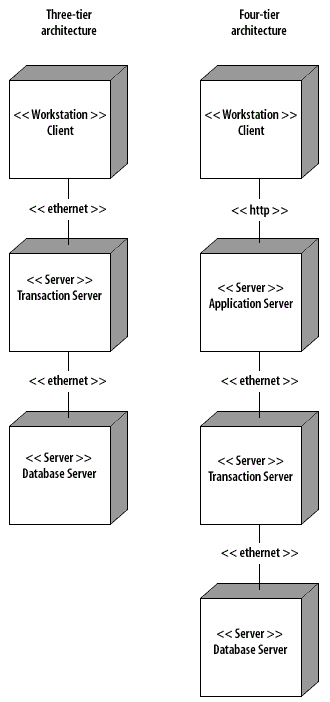
Below are two sample deployment diagrams, one for a three-tier installation and one for a four-tier installation. Please note however, that three- and four-tier installations do not have to install each partition on a separate machine. It is done that way here for illustration purposes.
However, it still provides a framework in which to capture hardware constraints that arise from the subsequent design activities.
Below are two sample deployment diagrams, one for a three-tier installation and one for a four-tier installation. Please note however, that three- and four-tier installations do not have to install each partition on a separate machine. It is done that way here for illustration purposes.
Systems Analysis Design
Deployment Diagram
Deployment Diagram shows the physical architecture of the system and can also be used to show software components being deployed onto the physical architecture.
Deployment diagram: A deployment diagram shows the architecture of a system from the perspective of nodes, processors, and relationships among them. One or more components typically map to a deployment node. In the context of J2EE, deployment diagrams are useful for modeling and developing the distributed system architecture.
If you need a review of deployment diagrams, go to the PDF file on the Resources page and get the file named UMLFundamentals_deployment.
Hardware configuration
As you proceed with the design you will become increasingly aware of the performance requirements for each partition.
These requirements will sometimes translate into hardware requirements in the form of more memory, processor speed, modem or network connection speeds, etc. These requirements can be directly modeled in the deployment diagram.