| Lesson 2 | The tools of object design |
| Objective | Identify the work products used during object design. |
Object Design Tools
Tools of object design
You have used most of the tools of object design already:
Review the relationships between the different diagrams in the MouseOver below.
- Object model: For many people this phrase is synonymous with class diagram. However, the model in a larger sense also includes the object diagram and package diagram.
- Interaction diagram: A generic term referring to the two UML diagrams that model object interaction (communication), namely the sequence and collaboration diagrams.
- Activity diagram: The UML version of a flowchart with added features to model concurrent activities.
Review the relationships between the different diagrams in the MouseOver below.
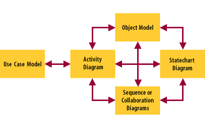
- The use case model identifies the communication between the actors and the system. The dialog is the basis for the interaction diagrams. The resources used to support the dialog become objects in the object model
- The use case descriptions may be modeled using activity diagrams that define the logic in the interaction between the actors and the system. Evaluation of the logic may result in changes to the scope and definition of the use cases.
- The activity diagram represents the logic for a use case or an individual operation.
- Whenever an operation requires significant logic, the activity diagram can be employed to help sort out the design of the operation. This in turn may result in the discovery of other smaller, reusable operations that may provide support for the larger more complex operations. Each operation also reveals the attributes that objects require in order to invoke an operation. These attributes are added to the class definitions for the objects whose purpose most closely matches the attribute purpose.
- The class diagram provides object definitions. Every operation and every attribute discovered by using the other diagrams are added to the class diagram. The class diagram is the definitive repository and the source for all code generation.
- The statechart diagram identifies actions and activities which translate into operations and operation logic. Each new operation is added to the class that defines the object.
- The statechart represents the life cycle of a single object. Every event that the object can respond to is represented along with the associated state changes and behaviors. State-specific behaviors are represented as actions and activities.
- The interaction diagrams may be used to derive the statechart diagram by identifying candidate states and the events that cause the transitions between the states.
- The interaction diagrams model the events passed between objects and in doing so identify the interfaces that the objects need in order to receive the events.
- Class definitions provide the objects that participate in the interaction diagrams. Interfaces discovered in the interaction diagrams translate into operations for the classes that define the participating objects. Each operation in turn identifies class attributes in the forms of input parameters (arguments) and return values.
- Individual scenarios in an activity diagram may form the basis for object communication in an interaction diagram. Interaction diagrams often identify complex interfaces that require further analysis using an activity diagram.
Design Work products
Interfaces discovered in the interaction diagrams translate into operations for the classes that define the participating objects. Each operation in turn identifies class attributes in the forms of input parameters (arguments) and return values.
Diagram interactions
In order to benefit from the diagrams, you need to understand the relationships between the diagrams.
The diagrams:
Note: Many CASE tools now provide consistency reports to compare the diagrams and highlight inconsistencies in the uses of specific model elements, such as events and objects. Others provide a scripting language that allows you to define your own reports.
- Present concise descriptions of what you know and decide about the system
- Represent different views of the system
Note: Many CASE tools now provide consistency reports to compare the diagrams and highlight inconsistencies in the uses of specific model elements, such as events and objects. Others provide a scripting language that allows you to define your own reports.
Object Design Tools - Quiz
Click the Quiz link to review the tools of object design. Object Design Tools - Quiz