The Statechart notation in UML (Unified Modeling Language) is designed to provide a powerful means of visualizing the dynamic behavior of an individual class or a collaboration of classes through states and transitions. Statecharts are particularly useful in modeling reactive objects, whose states are triggered by specific events. Here's an overview of the purpose and function of the Statechart notation in UML:
Purpose
Behavioral Modeling: Statecharts are primarily used to model the behavior of a system, focusing on how an object responds to various events by changing states.
Event-Driven Systems: They are particularly suited for event-driven systems where an object's state is changed by external or internal events.
Complex Control Logic: Statecharts help in understanding and managing complex control logic that would be difficult to grasp with traditional flowcharts or sequence diagrams.
Specification of Reactive Systems: They are ideal for specifying the reactive and responsive nature of a system where the timing and sequence of events are crucial.
Function
States: A Statechart diagram represents states of an object and the transitions between these states. A state is a condition during the life of an object during which it satisfies some condition, performs some activity, or waits for an event.
Transitions: Transitions show how the state of an object changes from one to another. A transition is triggered by an event and can be constrained by conditions, leading to a change in state.
Events: Events are external inputs that affect the system and can trigger state transitions. These can be signals, time events, changes in condition, or invocations of operations.
Actions: Actions are activities that are executed as a result of a transition. They can be associated with entering or leaving a state or with the transition itself.
Entry/Exit Actions: Statecharts can specify actions that occur upon entering or exiting a state, allowing for more precise control over object behavior.
Hierarchical States: Statecharts support hierarchical states (or nested states), enabling a high-level state to be broken down into finer-grained substates, which simplifies complex state behavior by reusing parts of the model.
Concurrent States: They can also model concurrent states within an object, representing independent regions of states that can operate concurrently, which is useful for modeling objects that can be in multiple states at the same time.
Overall, the Statechart notation in UML is a sophisticated tool for modeling dynamic behaviors and interactions within systems, making it easier for developers and designers to conceptualize and communicate complex state-dependent behaviors and conditions.
Statechart Notation
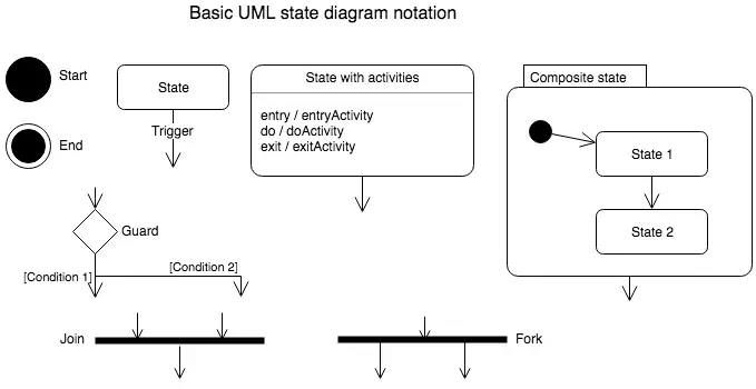
The statechart notation is fully described in the diagram below.
The diagram illustrates basic UML (Unified Modeling Language) state diagram notations. Here's a description of each element:
Start State (Black Circle):
Represents the initial state of the system or process.
State (Rectangle):
Represents a specific condition or status of the object in the system.
Transitions between states are triggered by events.
State with Activities (Rectangle with entry, do, and exit activities):
Shows the actions performed during the state.
entry refers to activities when entering the state.
do refers to ongoing activities while in the state.
exit refers to activities when exiting the state.
End State (Circle with Inner Dot):
Represents the final state of the system or process.
Guard (Diamond Shape):
Represents a decision point where conditions are evaluated.
Outgoing transitions are labeled with conditions (e.g., [Condition 1], [Condition 2]).
Join (Thick Horizontal Line):
Combines multiple incoming transitions into one outgoing transition.
Indicates synchronization of concurrent states.
Fork (Thick Horizontal Line):
Splits one incoming transition into multiple outgoing transitions.
Indicates the beginning of parallel activities.
Composite State (Large Rectangle with Inner States):
Represents a complex state that contains sub-states.
Includes an initial sub-state (black circle inside) and potentially other sub-states.
UML-state-diagram-notation
Review it as needed so that you can proceed with the remaining content of this module. Please pay close attention to the method used to derive a statechart from a set of sequence diagrams.
This technique will be the focus of the exercise for this lesson.
Building Statechart Diagram
In the following example we help you start the construction of a statechart diagram using a sequence diagram as your source. In mechanics rather than the complexity of the problem domain. But the same strategy can be employed as the problem domain increases in complexity.
State-chart Diagram1)
The diagram illustrates the process of starting a statechart for a system involving three entities: `aFacilityManager`, `aShow`, and `aShowSeat`. Below is a detailed explanation of the content in the diagram:
Description:
Objective
The goal is to represent the states and transitions of a ShowSeat object in response to events.
Steps to Start the Statechart Diagram
Identify the states: Determine the conditions or statuses the ShowSeat object can be in.
Identify the events: Define what triggers transitions between these states.
Draw the statechart diagram: Visually represent the states and transitions.
Merge diagrams: Combine individual diagrams into a unified statechart for the ShowSeat.
Key Notes
The object remains in a specific state until an event triggers a transition to another state.
In this diagram:
The aFacilityManager initiates the creation of a Show using the Create Show() method.
The CreateShowSeat() event creates the ShowSeat object.
The state of the ShowSeat object starts with the condition: “Not Priced, Not Selected, and Not Sold.”
The object does not exist before the CreateShowSeat() event.
Sequence
aFacilityManager invokes the Create Show() event, leading to the creation of a Show.
Once the Show is created, the CreateShowSeat() event is triggered to instantiate a ShowSeat.
After the CreateShowSeat() event completes, the state transitions to done.
2) Identify the events that trigger the transition between states.
3) Draw the statechart diagram.
4) Identify the states.
5) Identify the states.
6) Merge the new diagram with the previous diagrams to form a single statechart for the ShowSeat.
State Chart Notation - Exercise
Click the Exercise link below to work on the course project.
In this exercise you will build the statechart for the ShowSeat object.
State Chart Notation - Exercise